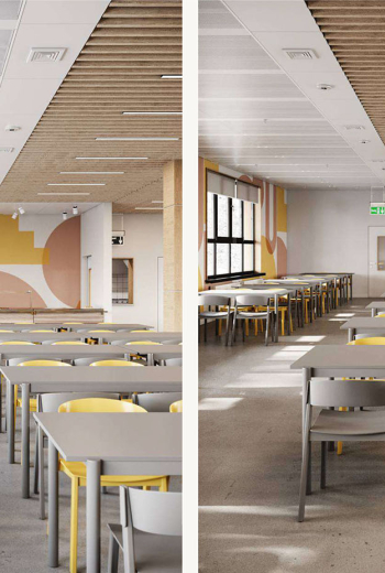
Suspended ceilings in the new design of school canteens: what can be improved?
KRAFT recommendations: what can be improved in the suspended ceilings of school canteens in...
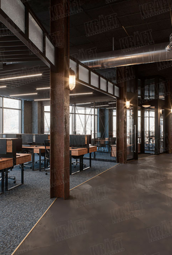
How the height of ceilings affects the comfort and performance of staff: practical recommendations (+ 9 photos)
How to create the desired office work environment by combining different types of false ceilings?...
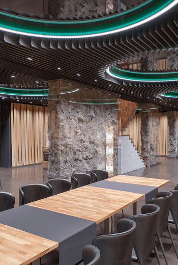
Multi-level suspended ceiling with mirror inserts (+9 photo)
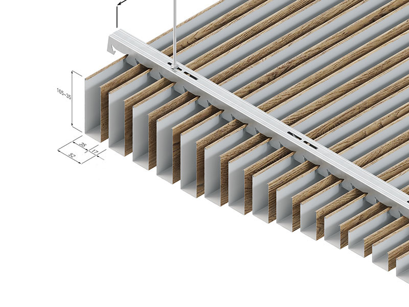
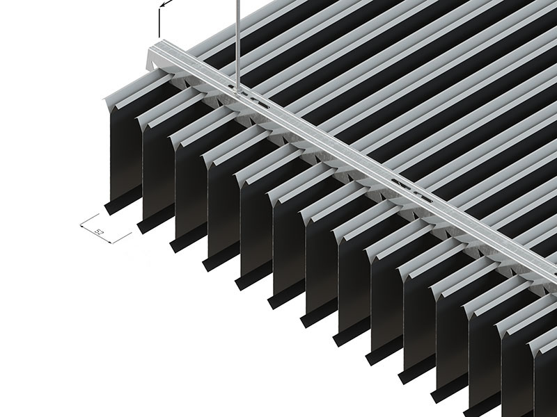
The design screen ceiling is made of plate battens combined with traditional materials in the...

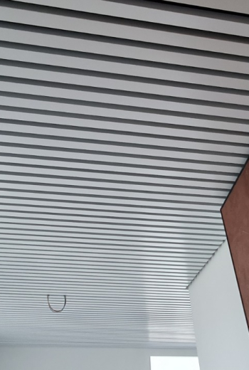
Apple-style office design and linear strip ceiling
In this room, notes of apple design are captured and the cubic ceiling perfectly fits into the...
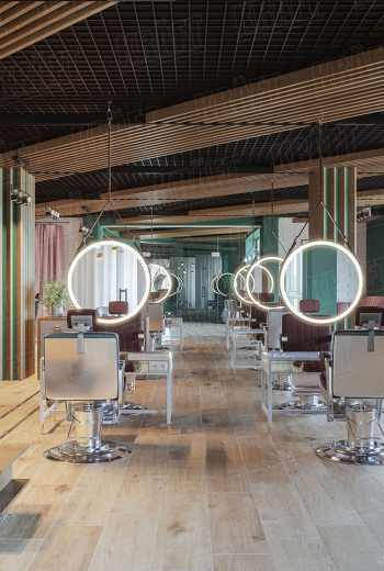
Everything should be perfect in a beauty salon - even a suspended ceiling (+8 photos)
An excellent design solution from KRAFT for a false ceiling in a beauty salon - open cell ceiling...
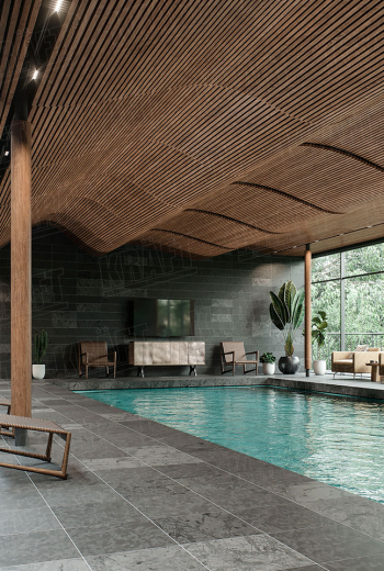
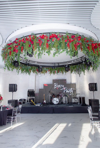
Wavy rail suspended ceiling - what you need for the pool! (+6 photos)
The original design of the suspended ceiling from a cube-shaped rail using a flexible traverse...

Suspended Ceiling Trends 2024 - KRAFT experts for the magazine “Architektura i biznes”
Within the special project "Ceilings and Ceiling Coverings - Trends 2024" the editorial staff of...
Recommendations for choosing a suspended ceiling for a cafe or restaurant
We bring to your attention the rating of suspended ceilings for catering establishments, compiled...

KRAFT cube-shaped rail ceiling in the restaurant "Puzata Hata" on Demeyevskaya
When you are one of the most famous restaurant chains in Ukraine, your position obliges you to...
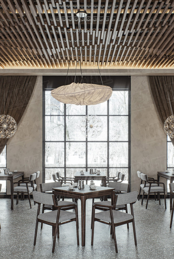
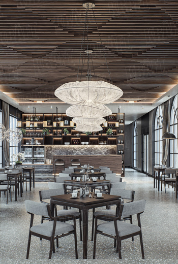
Suspended ceiling design that sets the tone for the entire room (+9 photos)
A creative design suspended ceiling in the restaurant hall, as evidence of the widest possible use...
Cube-shaped rail ceilings KRAFT in a prestigious residential complex in Romania (before and after photos)
Gratitude from the customer and the main advantages of the KRAFT cube-shaped ceiling for...
An extraordinary design solution with a volumetric slatted suspended ceiling (+13 photos)
A photo report from the Chagari restaurant is a vivid illustration of how to create memorable...
 English
  Українська